Every finding, cited to the pin.
Pincite checks your schematic against the datasheet of every IC on the board. Each issue comes with the datasheet's own words and page number, so your team acts on evidence, not guesses.
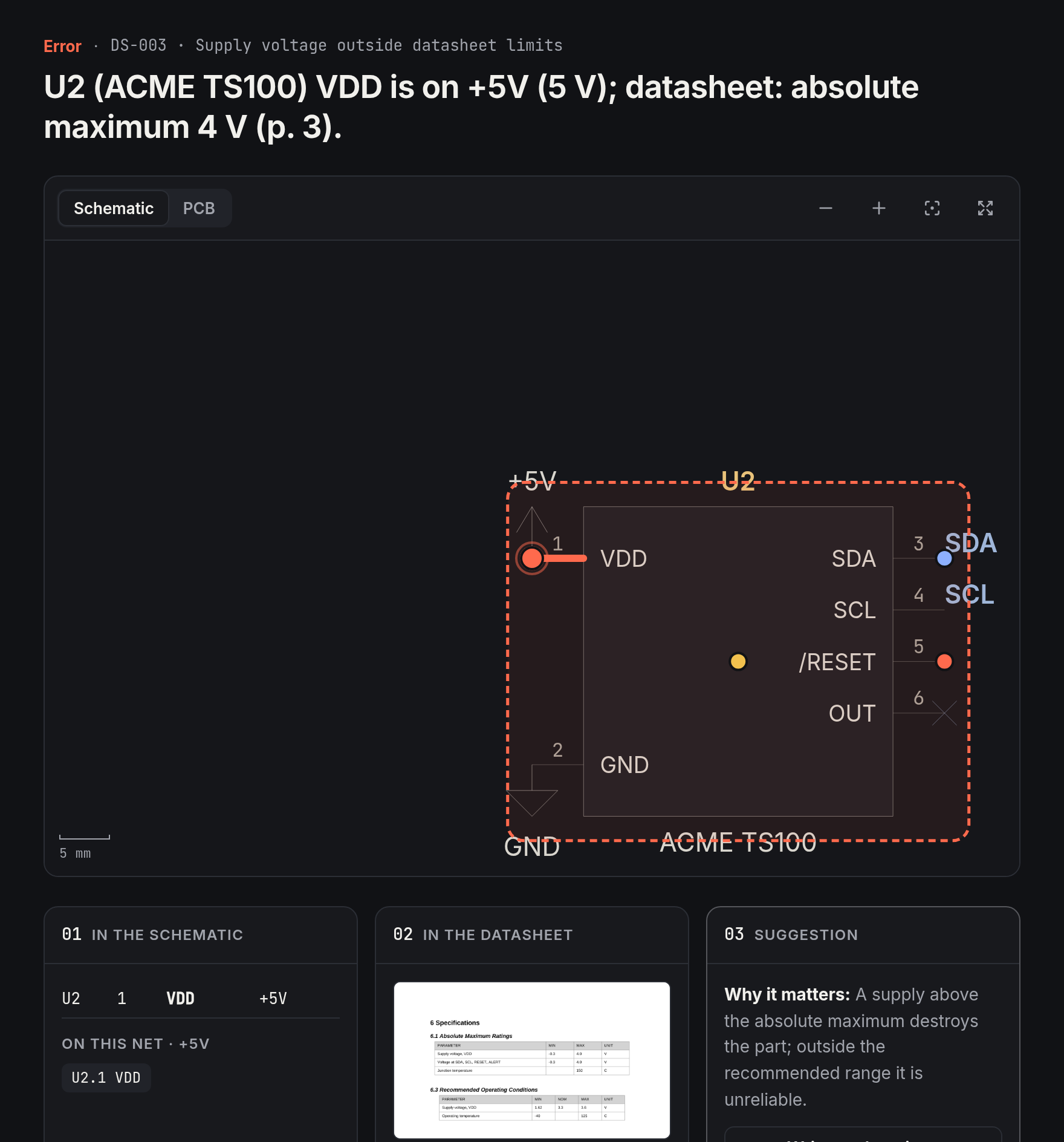
U2 VDD is tied to the +5 V rail; the datasheet's absolute maximum is 4 V.
01 · In the schematic
02 · In the datasheet
VDD: absolute maximum 4 V · recommended 1.62–3.6 V
03 · Fix
Move U2 to a rail that stays at or below 3.6 V. At 5 V the part is past its rating and can be damaged at first power-up.Your schematic and your board, with every finding on them.
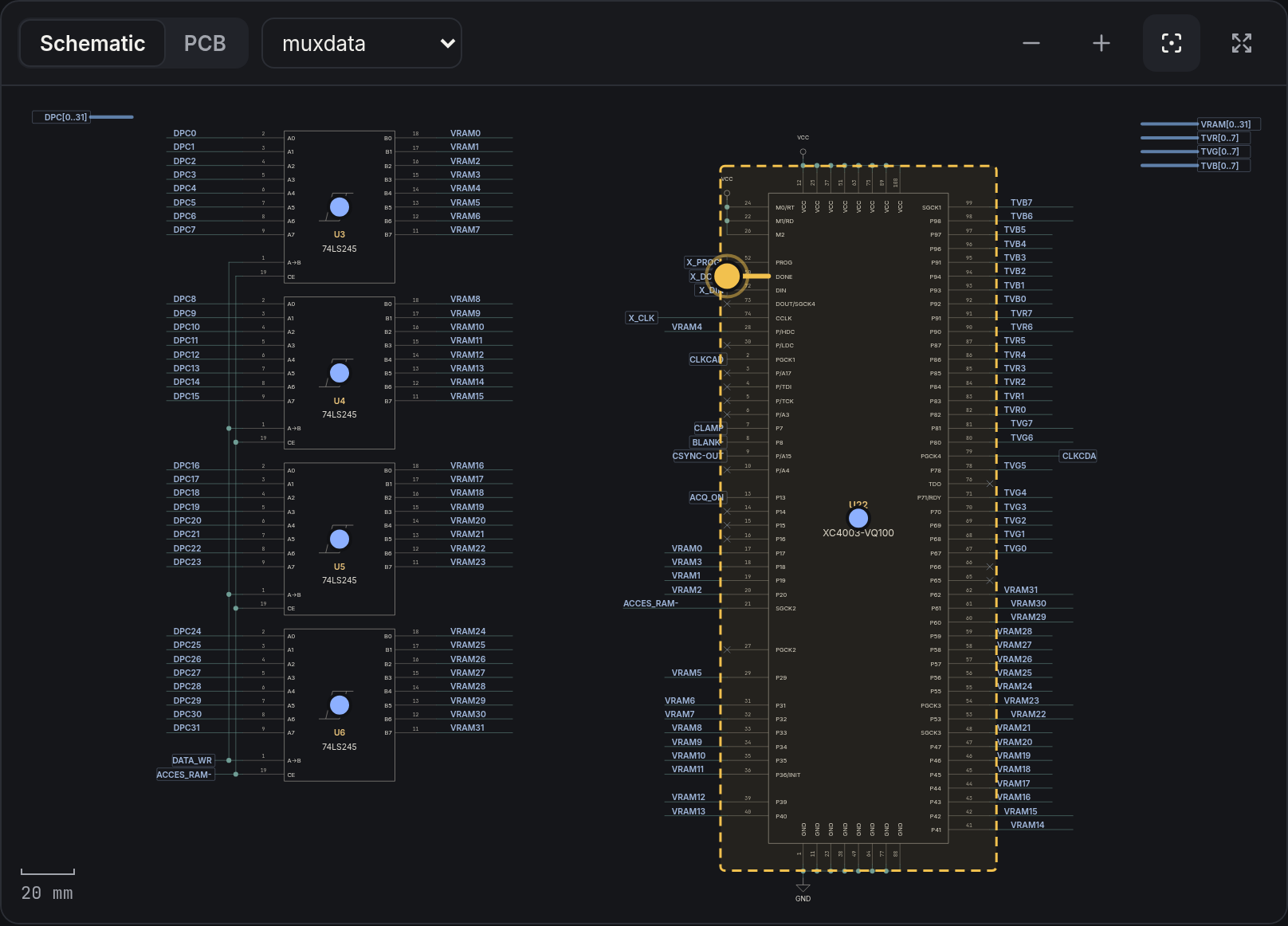
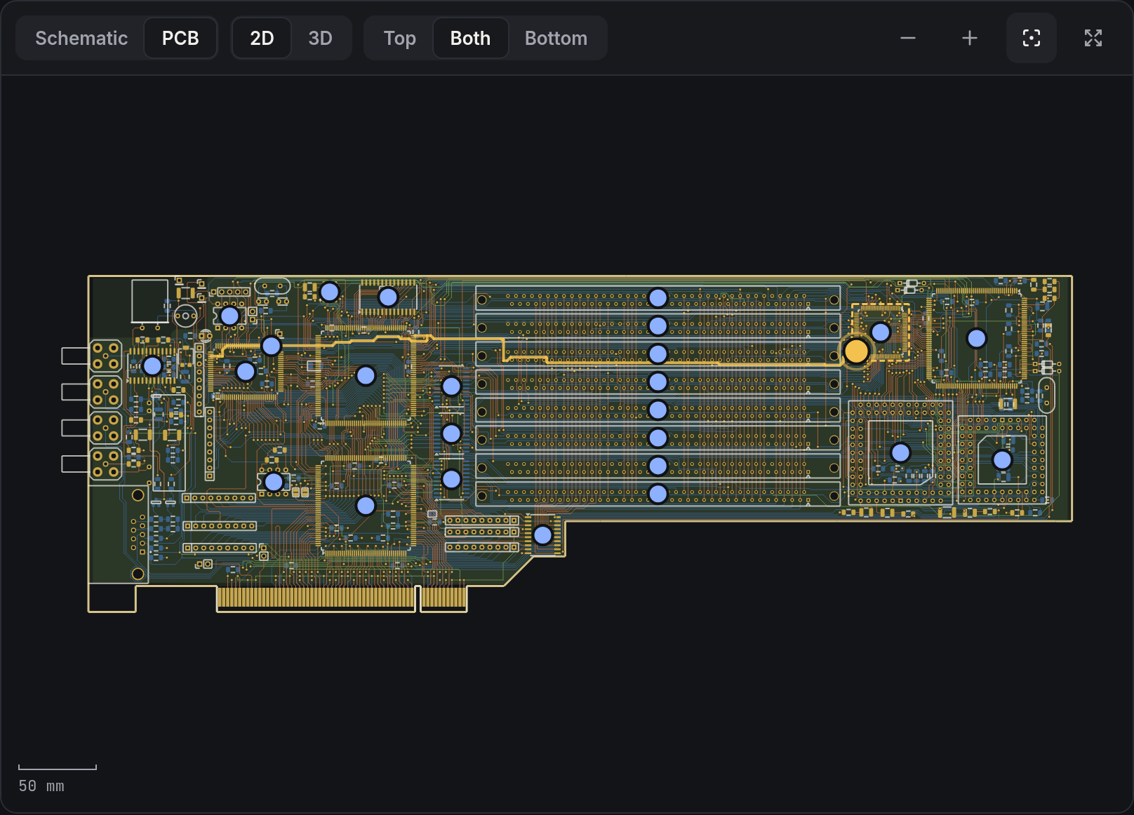
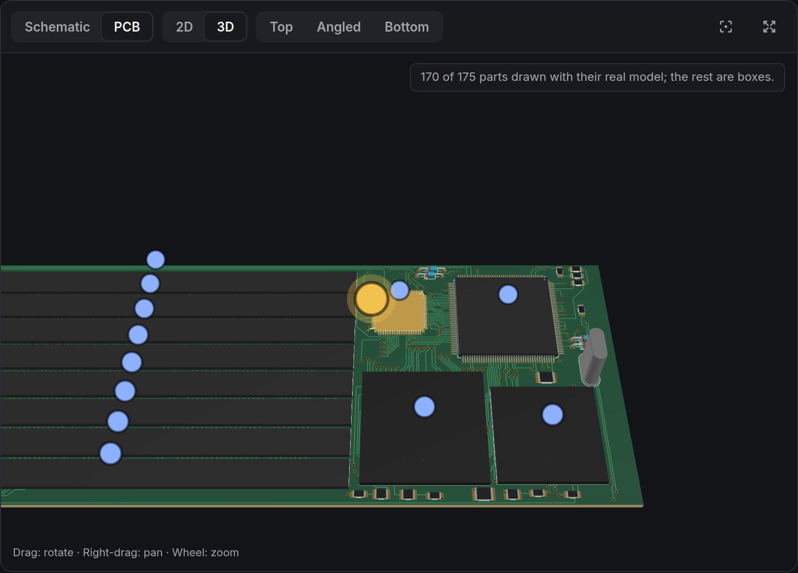
Pincite draws the design itself: schematic sheets, the PCB in 2D and 3D. Click a finding and it takes you to the pin, the net, the copper.
A senior reviewer that has read every datasheet.
Upload the design files you already have. No plugins, no re-drawing, no export scripts.
Reads your design
Schematic, netlist or board file from your EDA tool. Pincite rebuilds every net and pin, across all sheets.
Finds the datasheets
For each IC it locates the manufacturer's datasheet from the part number, or uses the PDFs your team keeps.
Checks the circuit against them
Feedback dividers, decoupling, pull-ups, logic levels, isolation, unused pins. A claim without a verified quote is never shown.
Knows your intent
Write down deliberate decisions ("no isolation needed") once; the next review respects them.
Built for sign-off
Revisions, approvals, firm-wide rules and an audit trail of who closed what, and why.
Your data stays yours
Run it on your own server with a local model, or use a cloud model when you choose.
What it found on a production design.
A 312-part industrial controller board, designed and already built by an experienced team. Details anonymised.
The regulator's circuit fits the fixed 5 V version, but the schematic names the adjustable one.
A bill of materials built from this schematic would order the wrong part, and the board would output 1.23 V instead of 5 V.
Both ground domains of an isolated RS-485 transceiver were tied together.
The team confirmed isolation was not needed here, which also means a cheaper non-isolated part would do. The decision is now recorded on the design.
A 5 V RS-232 transceiver drives a 3.3 V microcontroller input.
Flagged with the datasheet's sentence on supply matching, and what to verify on the MCU side.
An RS-485 driver's enable pin sits on a net named as an MCU input.
If firmware never drives it, the transmitter never turns on. Worth one question before fabrication.
Works with the tools your team already uses.
Including Proteus projects, read directly from the native file.
Send us a board you are about to fabricate.
We will review it with you and walk through every finding. If it catches nothing, you have lost an hour.
hello@pincitepcb.com